Radio Tower
N2OMDHere is a photo chronicle of the construction of my new ham
station at my country place 50 miles outside of Buffalo. My
good friend and Elmer, Dave KN2M, was of enormous help in the
design and implementation of the electrical and grounding
systems for the tower.
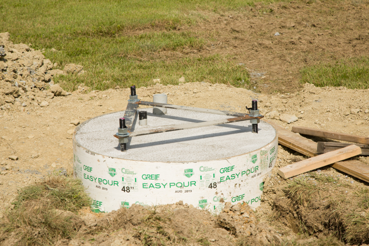
The tower kit I purchased was from Heights Towers of Florida.
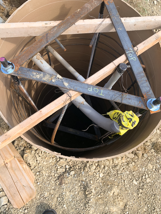
The first step was the excavation of the hole for the base.
Inside the sonotube is a rebar cage and three long threaded
rods.
One can also see two PVC conduits which will emerge from the
concrete base. The smaller is for electrical power. I had a
licensed electrician run a 20 A power line to the base of the
tower.
The larger 3 inch conduit is for my transmission and
control lines.
The concrete is poured leaving the threaded rods about 5- 8
inches above the surface.
Here is a closeup of the 3 inch conduit for the transmission
lines.
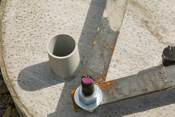
A clevis is mounted on each screw and the base is attached.
Throughout the entire assembly process the John Deere tractor
with pallet forks was essential for maneuvering each section
to the attachment point.
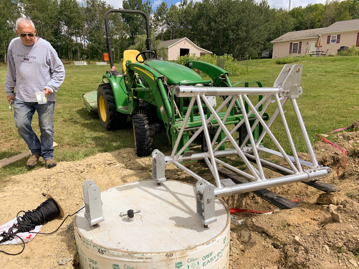
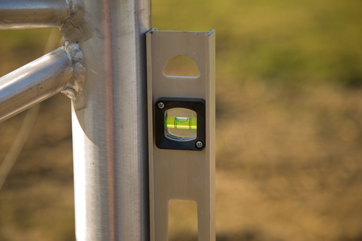
It is important the make sure the legs are vertical
I used the pallet forks on my tractor to lift the next
section so it can be aligned with the base.
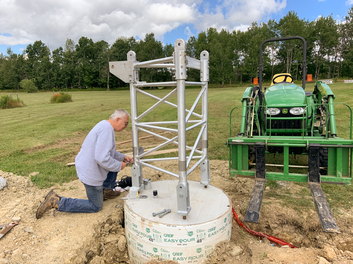
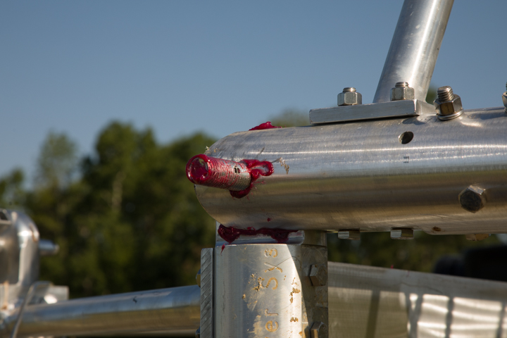
A liberal amount of grease was used to get the hinge joints
together.
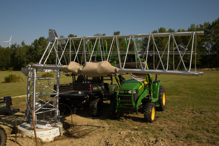
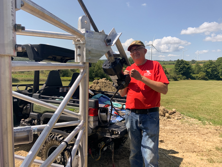
The motor and the screw are installed. This is how the tower
is raised and folded over. It takes about 10 min to go from
vertical to horizontal.
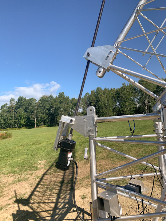
Once the motor drive was installed it was easy to fold the
tower over from vertical to 90 degrees horizontal.
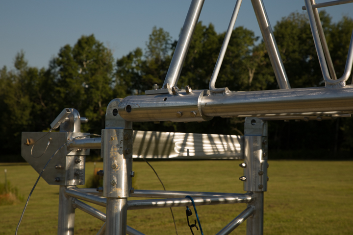
Each subsequent section was added until the tower was
complete. The beauty of the fold over system is that the
work could be done essentially ground level - or at least step
ladder height. While we had a contractor excavate the hole and
pour the concrete, the rest of the assembly was done by me and
my wife and our trusty tractor.
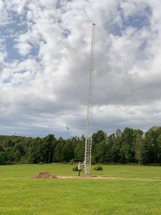
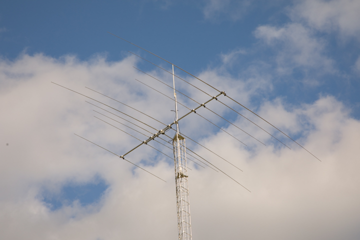
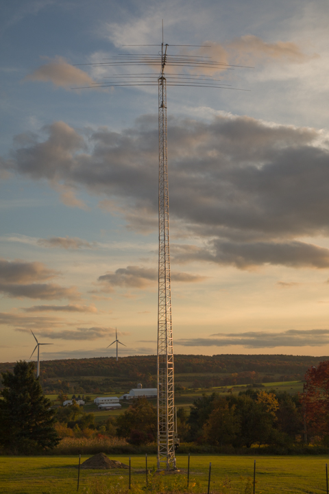
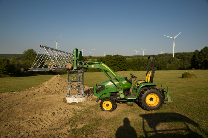
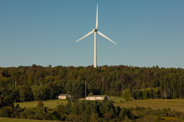
Our country place is in the middle of a windmill farm. Even
though the antenna seems huge when I am standing next to it,
it is only a quarter of the height of a windmill. Below is a
photo of our place with the tower and a windmill for
perspective.
When appearing before the zoning board to get a variance for
construction of a 75 foot antenna tower, one of the questions
asked will concern the visual and aesthetic impact of the
tower. I went to the board meeting armed with a similar photo
showing that the tower will be barely noticeable compared to
the windmills all around us.
The next step before mounting the antenna is installation of
the rotator.
Click the link below to view a video test of my rotator controller.
Rotator test 90 degrees